Selasa, 30 November 2010

Tips & Tricks

Understanding In-Place MTEXT Editor’s WYSIWYG Mode


The In-Place MTEXT Editor is a new function in ZWCAD 2010 that has been welcomed by many users. But when talk gets around to the “Always Display as WYSIWYG” option, some are left puzzled. The option can be turned on and off through the MTEXT Editor’s Editor Settings menu, as illustrated below. 
Let’s first get WYSIWYG out of the way. What on earth does it mean? It is an abbreviation for “What You See Is What You Get.”

Upon learning the meaning of the acronym, you might immediately guess that the ”Always Display as WYSIWYG” option means that, no matter the situation, the in-place MTEXT editor will always display text as it actually appears, in format and style. In most situations, the WYSIWYG option makes text editing easier and more convenient. For this reason, the option is turned on by default in ZWCAD.


So what happen when you uncheck this option? First, though, let’s imagine some extreme situations, such as these ones:

· The font size is much too SMALL. Unless you zoom in, you cannot read the text clearly at all.
· The font size is much too LARGE, making the text exceed the boundaries of the display area.
· The text is rotated too much.


These problems are illustrated below. 
 When you edit text that’s too large or too small, you have to zoom in and out every now and then. When text is rotated by too extreme an angle, perhaps you find yourself exercising your neck by twisting it too far. When these problems crop up often, these solutions become burdens. How do you deal with these annoying situations?

The simple way to solve the problems is to click the “Always Display as WYSIWYG” option, turning it off. After you do this, ZWCAD judges the size of the text being edited, and then adjusts it to a suitable display size automatically. This eliminates the troublesome zooming in and out. In addition, ZWCAD rotates text automatically, making it horizontal. These actions make the MTEXT editor more convenient for viewing and editing text.
After you close the MTEXT editor, the text reverts to its intended size and angle.


The figures below illustrate these three situations, in sequence, when editing with “Always Display as WYSIWYG” unchecked. 

When drawings have many pieces of large, small, and rotated text, I recommend that you turn off this option. You will find that it really helps you a lot. To end off, let me list the rules by which ZWCAD 2010 judges these situations:

1. Font size too small -- the height of single character is less than 10 pixels, display size.
2. Font size too large – the height of a single character is larger than half the height (or width) of the current view.
3. Rotated too far -- the text’s rotation angle is greater than 45 degrees
.

Senin, 29 November 2010

Tips & Tricks

Changing Multiple Layer Settings in Just a Few Steps

By Wesley Fenix,a CAD software user from Philippines

In ZWCAD 2010 I rediscovered a familiar friend, the Layer States Manager. I have found that it helps out a lot when I need to deal with many different layer settings.

Normally, we use layers in our drawings to control the properties and visibility of related objects, such as the color of all doors, the visibility of all windows, or the lineweight of all dimensions. We can even lock certain layers to keep objects on these layers from being selected or modified accidentally.

Imagine making these adjustments for many layers; it would be time-consuming and required great patience if you were to change the states of layers one by one with the Layer Properties Manager dialog box. But with the Layer States Manager, you can store customized layer settings in advance, and then apply them whenever you need.

Example Usage

I have a drawing with layers named Walls, Text, Dimensions, Furniture, Frames, Windows, Doors, and Plants. Objects are located on each layer according to the layers’ names, such as text on layer Text.

I need to create plots of the drawing customized for these situations:
1. Plot without any text or dimensions.
2. Plot without frames, text, or dimensions.
3. Plot without furniture or plants.

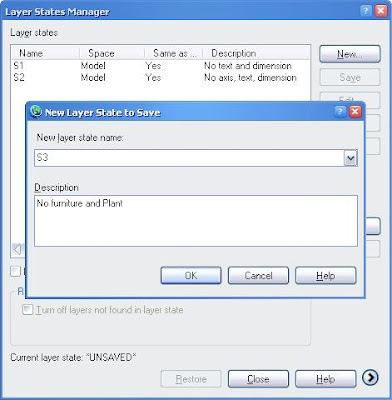
Should I turn layers off and on, one by one, for each type of plot? No! Instead, I let Layer State help me: I simply save the state of layers first, and then I return to them for each plotting situation. 

Here is how to customize layer states:

1. Open the Layer State Manager dialog box with the layerstate command.
2. Click the New button to create new layer states, and then name them S1, S2 and S3.
3. In the list box, select S1, and then click Edit button.
4. Turn off the Dimensions and Text layers, and then click OK to save the setting (state).
5. Repeat for state S2 (turn off layers Frames, Text, and Dimensions off) and S3 (turn off layers Furniture and Plants).
6. Exit the dialog box.

To plot the drawing without text and dimension objects, follow these steps:

1. Reopen the Layer State Manager.

2. Select S1 from the list box, and then click Restore to set S1 as current layer state.
3. Exit the dialog box, and then run the Plot command print all objects on the paper, except for the text and dimension objects.
The Text layer and the Dimensions layer are off whenever layer state S1 is restored.

Bonus Tip: You can export your layer states to a .LAS file, which means your customized layer settings can be applied to other drawings and on other computers. 

As you can see, Layer States Manager makes it very easy to perform multiple layer settings by few operations. Think of all the number of steps this reduces, there is no doubt that it saves your valuable time and calories. Let’s enjoy the smoother design experience along with ZWCAD 2010

Minggu, 28 November 2010

Tips & Tricks

My First Contact with ZWCAD - Convenient In-place MTEXT Editor

By Raphael Rodrigues, a new adherent of ZWCAD

Nowadays, touch screen technology is widely applied to all kinds of devices, such as handheld Internet tablets, mobile phones, and car navigation systems. But have you ever drafted on computer using your fingertips? Recently, I discovered a video on YouTube showing how the ZWCAD (TM) CAD system responded to touch controls; in response to someone’s fingers, it zoomed in and out, panned across the screen, made copies, and so on. You can see the video for yourself at http://www.youtube.com/watch?v=ho9kIOtJum0.
The video shows that ZWCAD responds quickly to finger touches and drags. It was so amazing that I decided to download ZWCAD 2010 and gave it a try.

To my delight, I found on the ZWCAD website a no-charge demo version of ZWCAD 2010 in the Portuguese (Brazil) language. To a Portuguese-speaking CAD user like me, Portuguese menus, toolbar tooltips, and command prompts provide a more comfortable drawing environment.

The ZWCAD website indicates that the in-place MTEXT editor is the biggest enhancement in ZWCAD 2010. I decided to try it out, and in doing so I found the in-place editor to be very user-friendly, because it has the same functions as does AutoCAD®. Let me summarize the benefits one by one:

1.    The text in the MTEXT dialog box looks identical to the resulting text in the drawing.

You are not supposed to experience abrupt situations such as this one: after you finish text editing and click the OK button, you find that the text in the drawing turns out to be too small or too big. ZWCAD displays text in the editor at the same size as it will appear in the drawing.

If you find the text in the dialog box too small or not in the right position, just use ZWCAD’s real-time zoom and pan controls to get the right view (roll the mouse’s wheel to zoom in or out; drag the mouse to pan). ZWCAD’s new in-place MTEXT editor fits the text to the drawing easily.

Furthermore, the special symbol displays its shape in the text editor’s dialog box. For example when you enter ‘%%d’, the degrees symbol displays immediately.

2.    Edit the text just like in the Microsoft Word application.

The new editor has additional features for adjusting text and paragraphs, such as multiple justification modes, various line spacing settings, adjustable tracking, and unlimited width factors. When you paste text copied from Microsoft Word, ZWCAD’s MTEXT editor keeps the original formatting.

3.    Convenient.

You may find it inconvenient to edit text in 3D views, such as SW isometric view, because the text editor and its text also maintain the SW angle. ZWCAD takes this into consideration by setting the Mtextfixed variable to 2. This forces the text to display horizontally, with a readable size, so that you can read and edit it more easily.

Another point of consideration is that ZWCAD asks whether to save your text changes when you press ESC while editing text in the text box. Careless users may appreciate this!
 
So far in my testing of ZWCAD, I have found that it is convenient and easy to use. In the future, I will have more experiences to relate to you.

Kamis, 25 November 2010

Tips & Tricks

Advanced 2D and 3D Design Tools in ZWCAD 2010


By Damian Chloe , an engineer and CAD user from Greece

Last time I introduced you my initial experiences with ZWCAD 2010. As I continued with my testing, I found more surprises that want to share with you. Let’s continue looking at some of the advanced 2D and 3D design tools.

The bigger the design project, the more helpful I find ZWCAD’s data management tools. Take Design Center and the Tool palettes, for example. Conveniently, they work together as visual tools from which I can find existing resources on my computer and reuse them.

In addition, the snap and autotrack features make designs much more precise.

Now, suppose you have finished drafting and detailing your design: what is the next step? Share it! Designs that are not understood or accepted by others have no meaning and so are of no value; it merely becomes a practice in design and does not materialize as real world objects.

So, how to share drawings? How to make others understand your ideas? How to communicate and collaborate with partners? ZWCAD answers these questions by providing many options:

  • You can publish drawing sheets as DWF files, or plot them to a variety of printers with different plot styles.
  • You can export drawings in a variety of file formats, which is useful when you want to place them as images in other documents and on Web pages.
  • You can render the drawings when 3D designs are meant to be shown in presentations. (You can plot the drawings to raster images, for which optimized JPEG and PNG printers drivers are provided by ZWCAD.)

And don’t forget the eTransmit feature, which is a favorite among team designers, for it collects automatically all related drawing and support files into a single package, including drawings, images, external references, and fonts.

I’ve talked about all these features in ZWCAD 2010, and so it seems to be very cool. But it still might not be perfect for every designer. If so, then customization is the solution!

Every 2D and 3D designer works in a specific design environment and needs to ensure the quality of the work. They need to boost their efficiency, something that is indispensable. When I tried entering the Customize command, ZWCAD understood it, and then guided me to configure the working environment to my liking. This included menus, toolbars, keyboard shortcuts, and aliases.

Checking the help documentation, I found that the program includes programming interfaces such as LISP, VBA, SDS, and ZRX. I used to program AutoCAD with AutoLISP and ARX, and so I checked to see if they are parallel to the LISP and ZRX in ZWCAD 2010. I ran some of my AutoCAD .lsp routines on ZWCAD, and found they worked! But when I tried my ARX routines, I ran into some problems. I contacted ZWSOFT’s technical engineers; they replied that ARX and ZRX are different but similar. The engineers made some modification on my files to make them run in ZWCAD 2010.


Overall, I found that ZWCAD 2010 is worthwhile, especially considering its functionality and price. When my friend asked me about ZWCAD 2010, I recommended it to him.

Rabu, 24 November 2010

Tips & Tricks

Tips on Editing Spline Curves with ZWCAD


By Carol Miller, a participant of ZWCAD Design Contest 2010

At the beginning of 2010, an article in a newsletter caught my eye. It was about the ZWCAD Design Contest 2010, and the topic for the contest was on designing the future. Winners would receive an iPod Touch or iPod Nano music player, and a license of the new ZWCAD 2010 software. The way I saw it, any unrestrained creativity is a futuristic style – all I needed to do was to exert my imagination to the greatest extent possible.

I drew a high-heeled shoes car, and to do this, the spline is the best tool for creating smooth curves. In addition, spline editing with the SplinEdit command makes the smooth curves even more perfect. As I created drawings for the contest with ZWCAD, I found some techniques that I would like to pass along to you as tips.

ZWCAD 2010 enhances spline editing with more options. Let me share with you a couple of tips and tricks in using SplinEdit.

Tip 1: Adding Points to Broken Splines

The shape of spline is defined by fit points and control points. When you select a spline, grips are displayed at the fit points; after certain operations, however, fit points are discarded and grips are instead displayed on control points. Moving the grip changes the shape of spline, of course, and more points means smoother splines.

Adding fit points is easy: just enter the SplinEdit command, and then enter F to choose the Fit Data option. However, after other editing operations, such as break and trim, the Fit Data option disappears; the spline no longer includes fit data. So how can you add points to a broken spline? Here is a tip that uses the Refine option. Follow these steps:

Command: splinedit
Prompt: Fit Data/Close spline/Move Vertex/Refine/rEverse/Undo/: (Type R, and then press Enter.)
Prompt: Enter a refine option [Add control point/Elevate order/Weight/eXit]/: (Type A, and then press Enter.)
Prompt: Specify a point on the spline : (With the mouse, pick a point on the spline.)

In this way, a control point is added to the spline.

Tip 2: How to Convert Splines to Polylines

Splines create nice smooth shapes, but CAM (computer-aided machining) programs cannot read splines – what a pity! A solution is to convert the splines to polylines using Flatten command. (Flatten is not the only solution; alternatively, you could save the file in R12 DXF format. Since the R12 format does not support splines, ZWCAD converts them to polylines automatically. The drawback is that such old file format can erase certain types of newer entities. For this reason, it is best to use the Flatten command.) 


Here is my drawing made with the Spline and SplinEdit commands:
http://cadcontest.zwcad.org/VoteDesign.aspx?id=62

Selasa, 23 November 2010

Tips & Tricks

My Experiences With the New ZWCAD 2010, Part I


By Damian Chloe , an engineer and CAD user from Greece


A friend recently entrusted me to test ZWCAD TM 2010 for his company. His firm is looking to buy CAD software, and so is considering ZWCAD. From his partners and from other people in the know, he had heard about ZWCAD, and so had acquainted himself with the software through Google and from www.zwcad.org. It is one thing to read positive comments; it is, however, another to subject the software to a series of technical tests by a professional – something that is necessary prior to making wise purchasing decisions.


And so I did. Here, I’d like to share with you my experiences in testing objectively the newly released ZWCAD 2010, a CAD software solution. (By the way, I tested the software on a computer running Windows 7 with 2GB RAM and a 2.8GHz CPU.)


At first glance, I was really surprised to see that it looked just like another AutoCAD ®! Its high compatibility with AutoCAD includes DWG and support for other resource files, commands and aliases, and the user interface. Although I have never used ZWCAD before, I found it very easy to master.


When I evaluate the functionality of a new CAD software package, I do so to determine how well it operates in terms of four aspects: (a) drawing and drafting features, (b) management and efficiency, (c) collaboration and communication, and (d) customization and APIs (application programming interfaces).


As CAD software, ZWCAD 2010 basically satisfies my need for sketching design ideas, because tools are provided for creating basic entities, such as circles, rectangles, and text. So that I can quickly visualize new designs, ZWCAD encourages me to reuse existing designs through externally referenced-drawings, inserted blocks, and placed OLE objects. Drawings become vividly colorful with raster images and hatch patterns.


In particular, I am very interested in the new in-place text editor, which includes a Text Formatting toolbar, a dialog box for formatting paragraphs, and a Display Options menu. When I tried it out, I found it to be very powerful.

 
There is so much I have to say about this software about the many features of ZWCAD 2010 that I’d like to describe them next time. In the meantime, you can download the software from the company’s Web site at www.zwcad.org and then try out the features I mentioned above.

Senin, 22 November 2010

Tips & Tricks

Improvements to Spline Editing in ZWCAD 2010

How time flies; the year 2010 is already here! I browse some CAD software websites as usual, and I am interested in a piece of important news : "ZWSOFT announces its fastest ZWCAD ever - ZWCAD 2010". No doubt this is an exciting message for me, a devotee of CAD.
 
In browsing the ZWCAD 2010 Web site (http://www.zwcad.org/cad-software/whatsnew.html), I found one improvement that really impressed me: the editing of splines. Splines are used in many applications, especially in the GIS (mapping) industry. For example, we can draw the contour lines on topographic maps in CAD with splines. Compared to ZWCAD 2009i, the SplineEdit command is greatly improved; in particular, the command’s Fit Data option is an improvement.

One of my best friends works at a geological survey design institute. He tells me that he uses the Spline command frequently to draw geographic contours, and that the spline editor improvements in ZWCAD 2010 will make his job more efficient. During our conversation, he shared with me his experiences of editing spline with grips. 
When he selects a spline in ZWCAD 2010, grips are now displayed on the fit points. He can use the grips to modify the location of the fit points, which modifies the flow of the spline.
After purging the fit data and changing the location of control points, the grips are displayed on control points instead. (When the spline’s control frame is turned on, then grips are displayed on both the control points and the fit points.)

The grips allow him to modify the fit points. He can delete, move, and add points to change the spline’s accuracy. Additionally, he can change the tolerance of the spline; when the tolerance is lower, the spline moves closer to the fit points.
From my friend’s introduction, I quickly grasped the improvements to spline editing in ZWCAD 2010. Meanwhile, I am looking through the other improvements in this version. 

Minggu, 21 November 2010

Tips & Tricks

Viewports in Paper Space

Typically, drawings are arranged in paper space before plotting. How can you use the original drawing in model space without making too many modifications? Viewports can help.
Let's take an architectural design that's been drawn in model space, such as the floor plan of an apartment. To show the details clearly, some areas should be shown at different scales. The question then arises: Do we need to copy these portions elsewhere in model space and scale them respectively, or can we manage them directly in paper space? Possibly, but not necessarily. We can readily make do with viewports.
Follow along with these steps:
1.Count the number of views needed for the layout.
2.Enter paper space, and then use the MVIEW command to create multiple viewports. A maximum of four viewports can be created at a time. If more viewports are needed, repeat the command.
3.To adjust the view, activate the viewport by double-clicking it. Then use the ZOOM and PAN commands to achieve the desired view inside the viewport. When zooming the drawing, use the XP option of the ZOOM command, because it zooms the viewport to a size relative to model space. For instance, 3XP makes the viewport view three times larger than the one in model space.
4.Once the view is established, lock it so that it will not be changed accidently. The Lock option is found in the MVIEW command.
After all views of the layout are adjusted, notice that the viewports have rectangular frames that are visible but are not necessary. How can we hide viewports' frames? Here is a trick:
1.Create a new layer named "Viewport Frame," for example.
2.Select all viewport frames, and then assign them to the "Viewport Frame" layer. You can use the Properties palette or the Layer droplist to do this.
3.Freeze the "Viewport Frame" layer, and the frames become invisible.
For other layouts, apply the same steps, and you will find yourself saving a lot of time. Viewports are a helpful tool, and can help improve your drafting efficiency when applied properly.

Kamis, 18 November 2010

Tips & Tricks

ZWCAD Tip: X and Y Ordinate Dimension in a Single Step

Q: Ordinate dimensions are essential elements of geographic drawings. Ordinate dimensions enable you to indicate positional information of objects and geometry. For my work, I almost always need to place x and y ordinates at the same time. Is this possible? 

A: Fortunately, ZWCAD makes it possible to create new commands through the use of the LISP application interface. With the help of the following LISP routine, it is possible to place x and y ordinate dimensions in a single step.

(User-defined variable names are boldfaced.)
(defun c:OXY()
(setq pt (getpoint "Input point:\n"))
(setq zg 5); text height is 5)
(setq x (car pt))
(setq y (cadr pt))
(setq xzb (strcat "X="(rtos x 2 2)))
(setq yzb (strcat "Y="(rtos y 2 2)))
(setq num (strlen xzb))
(command "text" (list (+ x 2) (+ y 2)) zg "" xzb "")
(command "pline" (list (+ x 2) y) (list (+ x 2 (* (* zg 0.85) num)) y) "")
(command "text" (list (+ x 2) (- y 5.5)) zg "" yzb "")
)
To use this code, follow these steps:
1. Copy and paste the above code to a Notepad file.
2. Save the file as OXY.LSP. (Be sure to modify the txt extension to lsp.)
3. Load the LISP program into ZWCAD using the AppLoad command.
4. Enter OXY to execute the function, like this:
                  Command: oxy
5. At the prompt, pick a point in the drawing.
                  Input point: (Pick  a point.)
This routine uses a fixed text height of 5 units. If this height is too tall or too short, modify the number in the  code, and then reload the routine into ZWCAD:
                  (setq zg 5); Change text height from 5
I hope that many AEC designers find this function useful, especially in the surveying and mapping Industry.

Sabtu, 13 November 2010

Tips & Tricks

How to Load Menu Files in ZWCAD

People use the Menu function frequently in ZWCAD, but different people have different requirements. They are not content with existing menu files and functions. In order to make their work easier and faster, they would like to customize menus.

1.Use “MENULOAD ” command
In ZWCAD, you can use the MENULOAD command to load and unload menus. After executing this command you can find the “Load/unload Customizations” dialogue box pops up as follows. To display this dialogue box you can also choose Tools→Customize→Menus.

Introduction the Function of Loading and Unloading Menus

a.Load menus
If you want to load menus, there are two methods to do that. First, you can input the menus’ name and path in the “File Name” text box. Second, if you forget the menu’s name, please press “Browse” button to choose the file you need. After that, click Load you will find the menu which you need is displayed in “Loaded Customization”. After closing this dialogue box you will find the menu file which you load has shown in the menu bar. For instance, we can know from the following pictures, the new menu “Mechanical lib” has been loaded and displayed in menu bar.

b.Unload menus
It’s not difficult to unload menus, please select the menus which you want to unload in the “Loaded Customization” box, and then press “Unload” button. After checking on the menu bar, you will find the menu file which you load has been deleted.

Note:
Please unclick “All Replaces”, if you just want to add some new menus to the menu bar.
Tips:
MENU command is different from MENULOAD command. MENU command loads new menus to replace the default one, and in the menu bar you can only find new menus. In addition to the same function as MENU command, MENULOAD command can add some new menus to the menu bar.

2. Import menu file
You can work at the following steps to display the customize dialogue box, choose Tools→Customize→Toolbars→ Menus, or use the command “TBCONFIG”.
Insert: this command includes five selections, i.e. Menu Item, Menu Sub-Item, Spacer, Context Menu Item, and Context Menu Sub-Item. You can insert one of them in the “Menu Tree”, but adding a spacer to the root menu is impossible.
Delete : choose the item which you want to delete from menu tree.
Import : click to import an existing menu file from another source.
Export : click to save the current menu to a different location.
Reset:  click to reset the current menu, rejecting any changes you have made.

Note:
Before you import the menu file, please choose Tools→Options→Files, and then choose the “Drawings File Search Path”. After that, press “add” button to add the path of menu file.

Jumat, 12 November 2010

Tips & Tricks

How To Input The Special Symbol In ZWCAD

By Karl Lee


As an engineer, sometime I need to input the special symbol such as ‘α’, ‘β’ and ‘ω’ in the drawing when using ZWCAD, here are some helpful tips which I take. I hope they are helpful for you too.

1.  Generally I launch character map in ZWCAD to input the special symbol (Mtextà right clickàsymbolà other), but sometime we may not launch character map because the character map is not installed in the operation system. Please try to add the character map in you operation system through either of these two ways:

a)  Copy the “Charmap.exe” file from other computer to your computer, paste it into the folder ‘system 32’ (C:\WINDOWS\system32).
b)  Reinstall the ‘charmap.exe’ in the operation system.
Startà Control panel à Add or Remove Programs àAdd/Remove Windows Componentsà Accessories and Utilities à Details àAccessories àDetails à tick and choose ‘Character Map’àOK. If there is no ‘Accessories’ component in the list, please try to copy charmap.exe from Windows 98 CD or download from website.

2. But it is also available to input the special symbol without the help of charmap.exe. Please take either of the follow methods as a solution.

a)   Copy form the Microsoft office Word.
Open a Word file, insert a symbol in the word document (Insert àSymbol), then copy the symbol, and paste in ZWCAD (MTextàright clickàpaste)
b)   Input the special symbol from the keyboard.
Inputs MTEXT or MT in command line to start Multiline Text Editor dialog box, Specifies the corner opposite corners to create a rectangle that defines the size and location of display of multiline text, Specifies the style for the multiline text: Symbol. Then input form the keyboard, click OK to finish. You will find that each letter you type from keyboard come out to be a special symbol. Cause the text style ‘Symbol’ is a special font style. It contains mathematic formulary, Grecian letter, number, operator, set symbol and other symbol. 

Kamis, 04 November 2010

Customer Success

Architecture

Irish Architecture Firm Prefers ZWCAD
Michael Collins is director of Michael Collins Associates (www.mca.ie), an Irish architectural practice. In a recent interview, Mr. Collins praised ZWCAD as “just as fast and reliable, or even better” than the existing system they have been using “at a very big reduction in cost.”

Established in 1988, MCA provides a full range of architectural, interior design, master planning, and project management services. The firm is involved principally in the areas of urban renewal, commercial, residential, educational, healthcare, and leisure, as well as buildings for the bloodstock (horse breeding) industry.

Using CAD software, MCA generates architectural and interior design services, and produces architectural design and construction drawings. Mr. Collins said his firm has about 30 CAD workstations that have been running another CAD system for the last twenty years. This year, however, they converted four of the workstations to run ZWCAD.

Mr. Collins explained how they are using ZWCAD 2009 for managing production. “We have been running ZWCAD successfully on the four workstations for the past six months. We use ZWCAD as our drafting tool to produce architectural designs and construction drawings.”

The other CAD system used by MCA is the market leader in Ireland. “Because of the lack of competition, however, it has become very expensive for us to maintain,” said Mr. Collins.

He gave a high evaluation of ZWCAD, confirming that the software met his firm’s needs and requirements. “It provides a cost-effective alternative to our existing CAD system. It has proved to be just as fast and reliable, or even better than our existing system at a very big reduction in cost,” he said.

“Standard ZWCAD even has features that are not provided by the more expensive program, such as the ability to edit blocks and external references,” he added.

Asked about the service, support, and training from ZWCAD Software Co. and EDA Systems, its authorized distributor in the United Kingdom, Mr. Collins gave a clear answer: “The service and support provided by ZWSOFT and EDA has been excellent,” he said.

“We are very pleased with its performance over the six months we have been using it. And we will continue to use it,” emphasized Mr. Collins. “This is the first time we have found a real alternative CAD software to our existing system.

MCA had been looking for a viable alternative to its existing CAD software package for a number of years. ZWCAD provided the first affordable, fast, and reliable alternative program that met their needs.

About Michael Collins Associates
Major clients of Michael Collins Associates include Ireland-based organizations in all fields, including American Airlines, Anglo Irish Bank, Deutsche Bank, Ericsson, FBD International, Fours Seasons Hotels, IBM, J M Huber, Lufthansa, Ernst & Young, KPMG, BCM Hanby Wallace, Department of Education & Science of Ireland, Department of Health & Children in Ireland, Dublin City Council, Enterprise Ireland, Fingal County Council, Ireland Food Safety Authority, and Ireland National Disease Surveillance Center.

Rabu, 03 November 2010

Customer Success

Manufacture

Altrust switches its CAD systems to ZWCAD
Altrust Precision Tooling Co. Ltd., is one of the top 10 mold manufacturers in Asia and is ISO-certified. For more than 15 years the company has been specializing in product design, mold making, machining, assembly, and prototyping.

Its products range from household appliances and office equipment to communication facilities and accessories for automobiles and motorcycles. These products sell well at home and abroad, and have won a good reputation amongst its customers. Recently, Altrust selected ZWCAD from ZWSOFT as its primary design tool.

 Altrust headquarter building

Mold making is at the top end of the manufacturing industry, and is usually characterized by high productivity, high maximum efficiency, and technical competence. With the recent downturn in the economy, Altrust found it necessary to examine its processes in order to maintain its leading position in the mold making industry and meet the requirements of its customers.

Prior to 2006, Altrust introduced numerous CAD software packages to its design and production departments. These advanced systems included Pro/Engineer, SolidWorks, Unigraphics, FreeForm, an ERP system, and a CAPP system, as well as an independently-developed 3D design system.

Altrust Adopts ZWCAD
In order to expand its business more efficiently, Altrust began to look for a single, more advanced CAD system that was capable of handling its mold making needs. Commencing in February 2006, Altrust evaluated ZWCAD through a series of intense benchmark tests. Following a successful outcome, Altrust selected ZWCAD as its main design tool. It found ZWCAD to be superior in the areas of DWG compatibility, program stability, speed, and five-star service. 

  Working environment of Altrust's engineering department     An Altrust engineer designs with ZWCAD

Altrust employs more than 200 engineers and designers in its R&D (research and development), engineering, and production departments. All are now taking advantage of the capabilities of ZWCAD for designing and modifying application modules for use in technical support and production.

The application development at Altrust falls into two parts: ‘module design’ and ‘module parts’. In the first, engineers are migrating all of the functionality and designs from the other CAD platforms; in the second, they are developing new functionality on the ZWCAD platform.

Due to the strong technical support provided by ZWSOFT, Altrust was quickly able to solve many technical problems, thereby ensuring that model customization continued smoothly. 

 Processing chart of electronic die mold 
Processing chart of hand-washing liquid mold

"ZWCAD has the powerful features and high performance that we were looking for. Our engineers find that they work very easily and conveniently with it, due to its compatibility with and similarity to AutoCAD," said Mr. Xie Ye Qing, Director of Altrust's R&D department. "What’s more, we found great innovations in ZWCAD, such as its dynamic input capability.”

"Due to ZWCAD’s fast upgrade schedule and rapid development program, since our first installation in 2008 we have now commisioned it on most of our computers," he continued. "What we particularly like is the API (application programming interface). The R&D department is now testing the speed and performance of ZWCAD's APIs so that we can gradually move all of our processes to the ZWCAD platform.”

The Future of ZWCAD in the Mold-Making Industry
Mold making is the cornerstone industry of Hengli Town, Dongguan. The town is home to more than 600 mold-making companies, headed by Altrust. Due to the global financial crisis, however, it has been confronted with declining orders, along with pressure on product pricing. The intense competition has compelled it to shorten its production cycles. In these circumstances, it is essential for it to adopt advanced CAD technology, and ZWCAD has proved to be the optimal choice.

By applying ZWCAD, Altrust's efficiency in model design and production has been greatly improved, and the production cycle also been shortened. To ensure the continuation of these benefits, ZWSOFT is committed to providing innovative, reliable and cost-effective CAD solutions which will help mold manufacturers to further improve their production efficiency and product quality.


Selasa, 02 November 2010

Customer Success

Engineering

Polish Engineering Company Adopts ZWCAD for Tooling Design
Invenio Poland (www.invenio.pl) is an automotive engineering company located in Poland. Recently interviewed on the company's use of computer-aided software, managing director Jerzy Mydlarz praised ZWCAD as “a good CAD tool with a competitive price.”

As a part of Invenio International Group, Invenio Poland provides a full range of product design services, manufacturing, and engineering services. The firm is involved principally in the automotive industry, specifically in the components sector.

Invenio adopted ZWCAD mainly for tooling design. Mr. Mydlarz gave high marks to ZWCAD, and confirmed that the software meets the needs and requirements of his firm. “The similarity to AutoCAD is the biggest advantage,” said Mr. Mydlarz.

 This model describes the prototype of a vehicle designed in ZWCAD.

“ZWCAD meets our requirements. Without it, I don't think we could get more business or complete more work faster. The reasonable price of ZWCAD software is a significant contribution to our profitability.”

He underlined another very important feature: having the license of ZWCAD on a USB dongle. This lets the staff of Invenio use the software everywhere – at work, at home, on business trips, and so on.

He is also very pleased with the support provided by ZWSOFT and its authorized distributor in Poland, Uslugi Informatyczne. “Specifically, I am satisfied with the cooperation of the local ZWCAD distributor”.

This test vehicle was designed by ZWCAD. Its purpose is to perform tests for the doctoral dissertation of one of Invenio's workers.

About Invenio
Invenio was founded in 1986 in Russelsheim, Germany to perform product design, manufacturing engineering, and quality services for the automotive industry. The Polish division was established in 2002, with headquarters in Bielsko-Biała.

Invenio services are linked: product design, quality, supplier quality development, human resources, and process development. Some 95% of their work is performed for the automotive business, especially for producers of vehicle components.

Senin, 01 November 2010

ZWCAD Fitur

Customization & Programming

Customizing dan Programming ZWCAD

Customizing the Interface
Anda dapat menyesuaikan dengan mudah interface ZWCAD. Anda dapat memodifikasi menu, toolbar, shortcut keyboard dan command aliases untuk kebutuhan maupun standar kantor Anda.
  
Programming dengan ZWCAD
ZWCAD menyediakan interface aplikasi programming yang nyaman, seperti LISP (serupa AutoLISP), VBA, SDS (serupa ADS), dan ZRX (ZWCAD Runtime Extension, serupa ARX). Dengan interface ini, Anda dapat mengembangkan desain khusus dan aplikasi drafting untuk memenuhi kebutuhan Anda secara lebih sempurna.