Kamis, 30 Desember 2010

Tips & Tricks

Creating Designs Easily with Parametric Tools

By Mariajose Revert, an engineer and CAD software user

As a mechanical engineer, I need to deal with a lot of mechanical drawings. Most of them have orthographic views, which are also known as three-view drawings. The three views show the front, side, and top views of models. In the past, if I needed to edit the model, I would have to edit it in each view. It was rather troublesome, and the process bothered me a lot.

But I recently learned that ZWSOFT had announced their new 2011 version of ZWCAD with parametric functions. So I downloaded the software and tried it out. What can I say? These functions are really amazing!

OK, let me show you how I utilize this feature to ease my workload. Here is an example drawing:

It’s a simple orthographic drawing of a mechanical part. Currently, the entities are not held in place by any parametric constraints. So each time I move a line, the object is broken.

To start off, I turn on the parametric toolbars by right-clicking on any toolbar open in ZWCAD. And there I find three of them: Geometric Constraints, Dimensional Constraints, and Parametric.

I can get started by simply clicking the Auto Constraint button on Parametric toolbar and then apply it by selecting the entire drawing. Immediately, ZWCAD shows the many constraints that it added to the drawing automatically:
 

If I now move any object in the drawing, all related ones will also be updated. But this is not enough, because I know that I have to add a few specific constraints manually.

First, though, I find that there are too many icons in the drawing, so I click the Hide All Constraint Bars button to make them disappear from view.

Next, I examine the drawing. Because the two circles (actually, they are holes) are symmetric about a center line, I can add a symmetric constraint to them. I click the Symmetric Constraint button on Geometric Constraint toolbar, and then select the two circles, and finally select a line of symmetry. After that, when I move one circle, the other moves as well, just as if they were mirrored.

I did the same for the two lines shown in red by the figure below:
 In orthographic drawings, the length of the left view should equal to width of the front one. I can add an equal constraint to the two lines. I just click the Equal Constraint button on Geometric Constraint toolbar, and then select the two lines show in red, below:
 It is the same for these two lines as well:

With these constraints added manually, I have completed the geometric constraint portion of the design. When I move any part of an object, the related objects are moved together, which guarantees that this is drawing remains orthographic. The next stage involves dimensional constraints.

The first thing I want to do is to control the radius of the half-circle at the top. I just click the Radial Dimension button on the Dimensional Constraint toolbar, and then select the arc. ZWCAD shows me its current value with a parameter, just like shown by the figure below:

I give it the value that I want, and then press Enter (or click somewhere else) to confirm. The value drives the size of the object, thereby changing it. This is the most significant difference between a constraint (or dynamic dimension) and a normal dimension.

Next, I need to control the distance from the hole’s center to the part’s edge. I can add a vertical dimension here, clicking the Vertical Dimension button, and then selecting the center and the endpoint of the edge in the top view:
Then I add a horizontal dimension in the left view, and then change the value to d1:  
Here I find another advantage to dynamic constraints: I can define the relationship between two dimensional parameters through the use of mathematical expressions.

After I place the series of constraints illustrated above, I again tried using normal editing commands on any object in the drawing, such as moving and stretching. It is amazing to see everything move and stretch together. The drawing stores the relationships permanently as an orthographic drawing, and will never break them up. And for those objects with dimensional constraints, they cannot stretch; I can change them only by be editing their dimension values, so I needn’t worry about doing anything wrong with these fixed objects.
 

Rabu, 29 Desember 2010

Tips & Tricks

Tables Are Now Available in ZWCAD 2011

By Alexander Martinez, an engineer and CAD software user
Today I got the news that the ZWCAD 2011 became available. There are many interesting features in this new version, including tables – one for which I have been waiting for years. I immediately contacted my local sales rep to ask for a copy so that I could take a look at this new function.
To my surprise, I was pleased to find out that the new table feature in ZWCAD 2011 really will help me save a lot of time. As an engineer, I have to produce detailed drawings together with documentation. In previous versions, I found it tedious and time-consuming to create tables. I had to draw a lot of horizontal and vertical lines to create the frame of the table and then insert text or mtext into each cell, one by one. Then, it was even more difficult to edit the table, such as merging two cells – something that was almost impossible to do with the older versions. For many years, it was a real pain for me.
 Now with the new table feature, it is easy to create tables in ZWCAD. There are two ways to create table: you can either create a new empty table, or construct one from an existing Excel file. This is exciting news for me, because I prefer to use Excel to process large amounts of information in my drawings.
Creating Tables

If the table is not very complex, I don’t use Excel to create the table. Instead, I use another way, which is to say, from an empty table. First, I customize the table style to my liking using the TABLESTYLE command. Here I can set almost any properties for the table that I like. For example, I can set table direction to be up or down. I can set different styles for the title, data, and header rows. For each one, I can set a series of properties, which I access easily through the three tabs shown in figure 3 below.
When I need to make big changes to tables, I am more likely to edit them in Excel. Here I find another command useful, TABLEEXPORT. With this command, ZWCAD converts the table in the drawing to an Excel file. I edit the data in the spreadsheet, and when I have finished the modifications, I import the Excel XLS file back into my drawing with the TABLE command.
Editing Tables
Of course, sometimes I need to make modifications to the table, such as editing text cells. It is easy for me to accomplish this in ZWCAD 2011 through the new Table editing toolbar. It provides me with many operations fundamental to tables, such as adding and removing rows and columns, merging cells, and formatting text.
Here are a couple of tips you might find useful when working with tables in ZWCAD 2011:

Tip 1: In figure 4 above, you can see that when a table cell is being edited, it highlights the row number (1) and the column letter (B). If you don’t like the highlighting, you can turn it off by setting system variable TABLEINDICATOR to off.

Tip 2: After I create a table, I sometimes need to adjust the height between rows or width between columns. What I do is just drag the grip (shown as a blue square in figure 5) around the selected cell . Try it yourself, it is fun!
I was very excited to try out on the new table feature in ZWCAD 2011, and now I cannot wait to upgrade my software. I did find, however, that a few functions are not supported for now, such as Insert Formula, but that’s OK; nothing is perfect at the beginning. I am confident that ZWCAD will be improved step by step, and will surprise us pleasantly in subsequent releases.  

Selasa, 21 Desember 2010

Tips & Tricks

Using Fields with Drawings in ZWCAD 2011

Now you can fill templates, sheet sets, and custom fields with data from drawings that update automatically. ZWSOFT has added “field text” to the latest version of ZWCAD 2011 beta. When you use field data as part of a sheetset in a drawing, you can control nearly every aspect of how users create and manage drawings during the life cycle of a project. The command can be accessed by entering Field at the command prompt, or by selecting Insert Field from the Insert menu.

The Field command in ZWCAD can be used to extract and present data from drawing files as text fields. Fields can be embedded in mtext, tables, attribute definitions, and so on. For example, if you use text in your drawing over and over again -- such as the current date, the drafter's initials, and/or your company’s name and address -- you can save time and improve accuracy by placing the data as fields with the Field command. You do not have to memorize or remember the information, because when the values are updated or changed, ZWCAD changes the text automatically, instantly.

At any stage of the drawing, you can change the properties of the drawing, such as text height and text style, through drawing properties that create the custom properties. If you cannot find the custom field content that comes with ZWCAD, you can add custom field through the Custom Tab of the Drawing Properties dialog box. These custom fields can then be used in other parts of the drawing through fields.
In ZWCAD drawings, field text has a gray colored background. This is a visual indicator that the text is a field; the gray background can not be printed. Once a drawing is customized with fields, you can save it as a DWT template drawing, and then have it available for any other drawings based on that template.

Here is how to change text to fields: double click the text to edit it, and then from the formatting toolbar click on the Insert Field button. This brings up the Field dialog box, from which you can select the categories and options to add fields to the text


Similarly, you may use the AttDef command to create an attribute definitions made of fields. This can be done through the Default Text item of Attribute Definition dialog box.

Even when an attribute consists of a field, users can still override the field's automatic value. An example of this is the date in a drawing’s title box. You can use a field, which always reports today’s date; you might, however, decide to freeze it to a fixed date when necessary.


Senin, 20 Desember 2010

Tips & Tricks

Making 2D Profiles from 3D Solids With ZWCAD2011

By Raj Ganesh, an engineer and CAD software user

I got some exciting news today: ZWSOFT announced that ZWCAD 2011 Beta had the SolProf command. I became familiar with this feature years ago when I was learning how to use AutoCAD software. I have been waiting for this function when I switched to ZWCAD with the 2007 version. And now my wish comes true with ZWCAD 2011. SolProf is short for “solid profiles,” and is only for 3D designers; probably, most users may not concern about it. Anyway, I like it and make good use of it in my designs.

I would like to share with you how I use SolProf. If you use SolProf in other ways, I hope that you share the techniques with us, too.


Here is the typical use for this command. I have mechanical drawings of 3D objects. I know that if I am going to manufacture this component, I have to convert the drawings to 2D plans of several different viewpoints, and then add dimensions to size the parts. For example, the figure below shows the drawing of a 3D part.


1. The first step before using SolProf is to split the drawing into four viewports to show three sides (top, side, front) and an isometric view. This arrangement clearly shows what the object looks like. 

2. The second step is to start the SolProf command, and then apply it four times, once on each viewport. I’ve captured the command history so that you can see that it is not very complicated.

___________________________________________________________________________
Command: SOLPROF
Select object: (Choose object in one viewport.)
Entities in set: 1
Select object: (Press Enter to continue.)
Display hidden profile lines on separate layer? [Yes/No] : (Enter Y.)
Project profile lines onto a plane? [Yes/No] : (Enter Y.)

___________________________________________________________________________

I would like to give a brief explanation about the meaning of the last two options:


“Display hidden profile lines on separate layer? [Yes/No]”


Y means that two blocks will be created, one for visible lines, and the other for the profile’s hidden lines. (Hidden lines are those at the back of the part.) I recommend that you enter Y.

N means all visible and hidden lines will be created as one block.

“Project profile lines onto a plane? [Yes/No]”


Y means the profile lines will be generated on one plane. I recommend that you enter Y.


N means the profile lines will be 3D.


The picture below shows the result after using SolProf. You can see that the profile lines were generated from the 3D object. In addition, several related layers were created to segregate profile lines, such as PH-1DF and PV-1DF. 

 3. What I did was get the profile lines from the 3D object. At this point, I could turn off original 3D object’s layers in the Layers Manager, and then change the line types and line weights of profile lines. See figure below. This makes the profile lines look nicer and makes them easier to work with. 
 4. Each viewport now has its own set of profile lines, making it convenient to modify them, such as adding dimensions and placing text.

If there were no function like SolProf, I could not imagine how I would go about getting profile lines. Probably, I would need to set the 3D object on a plane, and then trace its shape by drawing 2D lines or something like that. 

Minggu, 19 Desember 2010

Tips & Tricks

Using QSelect in ZWCAD to Filter Selection Sets

By Raj Ganesh, an engineer and CAD software user

Have you ever find worked with a big group of entities in complex drawings that contain text and a bunch of text styles that are scaled in metric units? As a result, the text appears tiny compared with the rest of the drawing.

Below is a screen grab of a Hobbing System in a mechanical drawing. The text is hidden behind the cyclonical object as part of the symbol. I would rather that the text be big enough to at least extend a bit beyond the cyclonical object, so that it is obvious that it is there. Some of the text consists of attributes, which are so small that they appear as dots.

To solve this problem, would you reinsert and redefine each of the “dots” manually, one by one? Although this method would work, I have found something far more efficient, something that is already built into ZWCAD. 

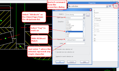
You may have noticed the QSelect button at right side of the Properties dialog box. By using QSelect from the Properties palette, you can quickly change the height of text .
Well, how could we go about carefully selecting the attribute objects using the Qselect command in ZWCAD? By using the trick of filtering. 
The workflow will be as follows: in the Quick Select dialog box, (1) select “Attribute” as the Object Type; (2) choose “Tag” in the Properties category; (3) in the Operations list, choose “Wildcard Match”; and (4) enter ‘*’ as the “wildcard” character in the Value field to select all attributes text containing that text. (In the Value field, you can enter any kind of text and wildcard combination, such ‘*DOT’ to select all text that end with the letters “DOT”.) Click OK to apply the filtered selection. 

So here we go… and in this case, ZWCAD selects all 61 matching attribute definitions at once. 

Now we use the Properties palette to alter the size of the text just by changing the value of the Height field. All 61 attribute definitions resize themselves. By editing one representation, we trigger the automatic updates of all others.
There it is. It worked really work very well for me!

Senin, 13 Desember 2010

Tips & Tricks

Making Better Use of the Right-mouse Button in ZWCAD


Many CAD systems use the command line to make drawings. This was especially true in early versions of software, when the keyboard played a more important role than it does today.

In ZWCAD, for example, the Space or Enter key can be used for ending commands and for restarting the last-used command. For example, you run the Line command, specify the first and second points with the mouse, and then you typically press Space or Enter to end the command. To begin drawing another line right away, you again press Space or Enter.

With the ongoing improvement in user interfaces, however, the command line is no longer as irreplaceable as it once was. In its place, the mouse increasingly plays a more important role in drawing and editing with CAD.

For example, did you ever notice that right mouse button can do the same work as the Space and Enter keys? Normally, pressing the right mouse button in a blank area of drawing displays a shortcut menu; right-clicking instead an entity brings up a content-sensitive menu that provides you with a fast way to modify your drawings easily.

As illustrated by figure 1, the shortcut menu lists the last-used command as the first item on the menu. You can click it to repeat the command; in addition, you can use the Recent Input submenu to select additional recently-used commands. 
But these are still not the fastest ways! You can change some settings in ZWCAD to make the right mouse button even more personalized and efficient. Here’s how to do this:

1. From the Tools menu, choose Options. (Alternatively, you can enter the Options command on the keyboard.)
2. In the Options dialog box, choose the User Preferences tab. See figure 2.
3. Click the Right-click Customization button. 

 4. Notice that the Right-click Customization dialog box contains many advanced settings, as illustrated by figure 3 below. Here are the settings I suggest that you can have a try:
a. Click the Turn on time-sensitive right-click option; a green check mark should appear, confirming that the option is turned on. This option allows you to specify that different click durations should execute different operations:
·   A quick right-click now means Enter to ZWCAD. You could use it to exit commands and to repeat the last command.
·   A longer right-click displays the shortcut menu, as before.
b. You can define the duration of the long click; the default is 250 milliseconds, which is a quarter of a second. Test the operation in a ZWCAD drawing; if you find the duration too long or too short, come back to this dialog box and change the duration.

5. Click Apply & Close to exit the dialog boxes.

With the time-sensitive right-click option set, you can make it behave as Enter on a short click and perform its standard function on a long click. This makes efficient use of the right-click button, because it now combines two functions onto one button.

You may not be used to this change when you first start to try it. You may find that every time you want to show the shortcut menu, you just click the right-mouse button quickly, and it executes the last command instead. But once you get used to this new setting, you will find drawing and editing becomes more efficient, because you don’t need to press Space or Enter any more. All you do is right-click, left-click, move, left-click, … and right-click at last.

So we can simply call it the “All in One mouse button.”

Minggu, 12 Desember 2010

Tips & Tricks

Make Use of Automatic Text Numbering Function in ZWCAD


By Johny Fuchs, an architect and CAD software user 

For some projects, it is important to place consecutive number markings in the drawings, especially in drawings of tunnels and pipes. For example, the figure below shows part of a drawing of an air conditioning system. This drawing has many pipes, and I have to label each one. 
Of course, I could use the Text command. But when the drawing requires many markings, then it becomes a pain to use the Text command to place text over and over and over again. While using ZWCAD, however, I found a more convenient command that helps me to perform this task semi-automatically. I found the Automatic Text Numbering function under in the Express menu’s Text section. 

To place a sequence of numbers in a drawing, follow these steps
1.Enter the Text command to place the first number.
2.With the Copy command, make copies of the number to the required positions in the drawing. In my case, I placed them along the pipes. (See figure below.) These numbers act as placeholders for the automatic numbering function.

3.From the Express menu, choose Text, and then choose Automatic Text Numbering (or just enter the TCount command). Select all the numbers, and then specify the starting value and the increment, such as 1,1. The first “1” refers to the starting value, while the second “1” refers to the increment. Finally, choose the “Overwrite” option so that the placeholder digits are replaced. The result is illustrated below.
 When only odd or even numbers are needed, then change the increment to “2”, with the starting digit as 1 (odd) or 0 (even), such as (1,2) or (0,2). The number markers will change to odd numbers or even numbers, as shown below.
So this automatic numbering function makes it quick and easy to change a batch of separate numbers, which cannot be easily input at one time. I think you will find it very useful for when you do this kind of drawing. 

Selasa, 07 Desember 2010

Creating Title Blocks with Attributes in ZWCAD

Title blocks are used to convey legal and descriptive information about drawings, such as the names of the company, designer, and owner, revision numbers, the drawing’s file name, and so on. (See figure below.) 
 Some people prefer to use ordinary text to fill in title blocks, but when the information is repeatedly changed, it may be easier to use attributes instead of text.

For example, when title block is used in other drawings, the file name changes, as well as the revision numbers, the owner’s name, and so on. When the title block is inserted as a block, then to modify the text, you need to explode the block to modify the text. Setting it up with attributes makes modification easier.
To see how this is done, follow these steps: 
To create attributes, enter the AttDef command.
 Provide the values for the Tag, Prompt, and Default Value fields. (Note that tag names must be a single word.) You can even specify the font and height separately for each attribute. For this tutorial, use the values provided by the table below:
TAG
PROMPT
DEFAULT VALUE
FONT
HEIGHT
JUSTIFY
Itemref
What item ref is this?
 Itemref
Arial
0.25
Middle Center
Title
What is the title?
Title
Arial
0.25
Middle Center
Filename
What is the drawing's file name?
C:/XXXXX.DWG
Arial
0.125
Middle Left
Revision
Which revision is this?
0
Arial
0.125
Middle Left
Scale
What is the print scale?
1"=XX"
Arial
0.125
Middle Left

After you enter the data for each attribute, click Define, and then enter data for next attribute.

Once all attributes are defined, click Define and Exit.

With the attributes defined, it is time to add the attributes to the title block. Use the Block command to create the block. You should select each attribute individually, taking care to select them in the order you want them to appear later when they are edited.

Once all of the attributes are selected, use a crossing window to select the entire title block as a whole. Hit Enter, and notice that the Make Block dialog box reappears.

Name the block, and then click OK
 As I mentioned above, it is easier to edit a title block that is set up with attributes, instead of text. You don’t have to explode the title block; to edit the attribute text, just double click the block or enter the AttEdit command to modify the values of the attributes. 
 Because it is a block, it can be used with other drawings; export the title block with the WBlock command, and then in another drawing use the Insert command to add it.

Minggu, 05 Desember 2010

Tips & Tricks

Whitepaper: ZWCAD 2010 Supports for DWG 2010 and Windows 7

by Ralph Grabowski  
ZWCAD is an IntelliCAD-based computer-aided design program developed since 2002 by ZWCAD Software Co., Ltd in Guangzhou, China. The company now claims over 180,000 users in 80 countries.

ZWCAD emphasizes such features as faster speed, support for Windows 7, DWG file format support, efficient drawing features, and powerful APIs. For this whitepaper, I tested two of the claims: DWG 2010 support and Windows 7 compatibility.


DWG 2010 Support

When I test DWG compatibility in non-Autodesk CAD software, I load a series of test drawings that identify problem areas. Generally, problems with DWG compatibility fall into two groups: (a) entities that are displayed incorrectly, and (b) entities that are not read at all.

After examining 45 test drawings, I found that ZWCAD 2010 performs remarkably well. Most entries are loaded and displayed correctly, even problem ones, such as proxies, gradient fills, complex linetypes, and filled multilines. (Multiline styles cannot, however, be edited.)


Associative dimensions are handled correctly, even new types, such as jogged and inspection dimensions. Three-D entities are displayed correctly, including 3D solids, 3D polygon meshes, and the new 3D meshes introduced with DWG 2010; 3D mesh objects cannot, however, be edited.

ZWCAD 2010 displays dynamic blocks as regular blocks. Stand-alone attributes are always displayed, even invisible ones, because it appears that ZWCAD converts them to text. Whiteouts are displayed with their borders only. Named plot styles appear as colors, instead of as patterns.

Among the advanced features of DWG 2010, ZWCAD does not reproduce geometric constraints, dimensional constraints, parameters, or materials. The source geometry is displayed correctly, but the additions are not present.


Windows 7 Support

I found that ZWCAD 2010 works correctly with Windows 7. There were no problems installing and running the software. On the Windows 7 taskbar, the ZWCAD button correctly displays its preview image and shortcut menu.
As a side note, I found the software to be speedy in loading and displaying drawings, even when dozens were loaded at a time. The only time I noticed a slowdown was when ZWCAD searched for missing fonts.

For more information, you can contact the company at http://www.zwcad.org.


About the Author

Ralph Grabowski is a technical writer who specializes in computer-aided design. He is the author of over 100 books and whitepapers on the subject, and edits the weekly upFront.eZine newsletter on the business of CAD. Mr Grabowski received his B.A.Sc. degree in civil engineering from the University of British Columbia.

Kamis, 02 Desember 2010

Tips & Tricks

Create 3D Solids Easily with Sweeps and Lofts

Three-dimensional modeling has gradually become a significant trend in CAD field over the last many years. The ability to model in 3D is now an important standard in judging whether a CAD program is feature-complete. Furthermore, the modern CAD program must offer convenient methods for creating 3D solid models. So we`d like to share with you something new and useful in ZWCAD: Sweep and Loft.

Both of these functions appear in the newly released ZWCAD 2010 Update Patch. They offer you quick ways to create 3D solids, yet provide you with a great deal of control over the final result.

Sweeping Solids

First, let`s try Sweep command. It creates 3D solids by sweeping 2D objects along a specified path. This means that a 2D object defines the cross section of the final 3D solid.

This command creates 3D objects with uniform cross sections. For example, the cross section of a torus (donut shape) is made from a circle, swept along a path that is also a circle. To use the Sweep command to draw a torus, following these steps:
In 2D plan view, first draw a larger circle as the path.


Next, draw a smaller circle as the cross section of the torus. See figure below.

 Run the Sweep command by entering sweep at the ‘Command:’ prompt in the command line, or by selecting from the menu, Draw -> Solid -> Sweep.

Following the prompts, select the smaller circle (as the object to sweep), and then select the larger circle (as the sweep path).

After you press Enter to end the command, notice that ZWCAD instantly draws the 3D torus. If you wish, use the Shade command to see it better, as illustrated below. 
 Creating Lofts

You might be asking, “How can I create solids with varied cross sections?” Good question! Another new command, Loft, provides the answer. It supports the use of at least two objects to define cross sections; in addition, it provides you with a dialog box to configure the shape of the loft.

Let’s use the command to an umbrella shape. Follow these steps:

In 2D plan view, first draw a small circle as the top of the umbrella.
Next, use the Polygon command to draw the outer edge of the umbrella as a large decagon (10-sided polygon). Ensure that the circle and polygon share the same center point, as illustrated below (left). 

 Change the 3D viewpoint to the left side.

Move the circle above the polygon, the distance being the height of the umbrella. See figure above (right). Remember to keep their centers on the same axis!

Now use the Loft command just like Sweep: Select the top circle as the first cross section, and the decagon as the second.

Specify the “Cross sections only” option, and then press Enter. Notice the Loft Settings dialog box, where you can adjust parameters to control the loft. 

The “Ruled” and “Smooth Fit” options are simple, because they have no parameters, creating solid surface directly.

The “Normal to” option means that the solid surface will be normal (at right angles) to certain cross section you choose.

The “Draft angle” option lets you control the start and end angles and magnitudes. (When you set both angles to 90 degrees, it is the same as choosing Normal to start and end the sections.)

Choose the “Draft angles” option, and then enter the values shown above. This will produce a shape like an umbrella.

Click OK, and then use Shade to render the simple umbrella that shows up before your eyes. 

So easy, isn’t it? This command can also produce lofts by path or guides -- similar to the Sweep command’s path. You can try it yourself in ZWCAD 2010 Update Patch.